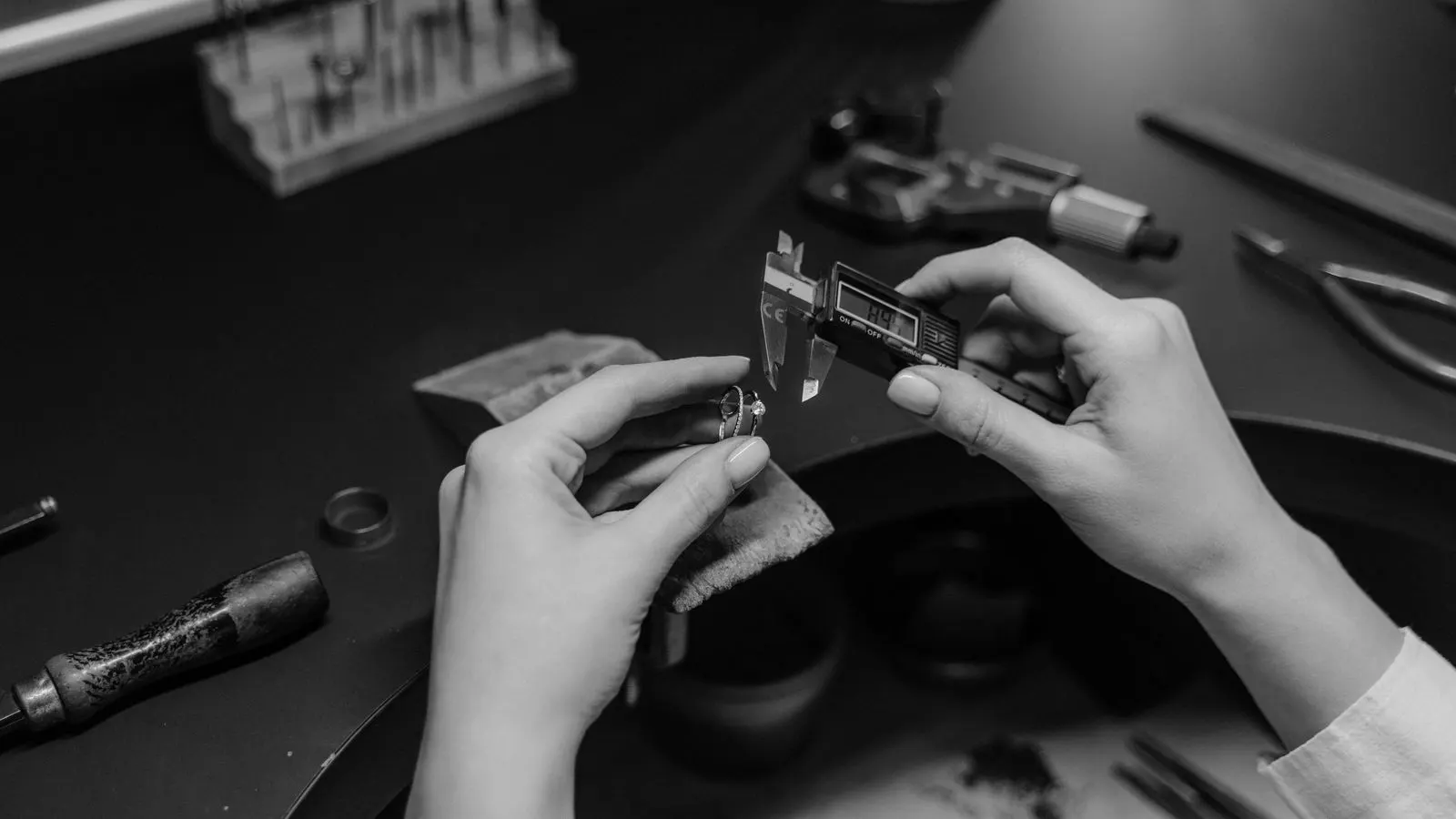
Checklist: Verifying Dimensional Tolerances
Use this audit checklist to verify casting dimensional tolerances. It covers inspection methods, gauging, CMM verification, and documentation to ensure received investment castings meet specified limits before release.
- Define tolerance limits clearly on the drawing, including GD&T callouts, to avoid interpretation errors during inspection.
- Use the right tool for each feature: calipers for small linear dimensions, CMM for complex geometries and hole patterns.
- Record measurements in a traceable format that links each part to its batch and inspection date.
- Flag parts with out-of-tolerance dimensions for rework or rejection before they reach assembly.
Confirm the Drawing and Specification Before Touching the Part
Start with the source of truth. Pull the final approved drawing, not a previous revision. Check the title block for revision level, effective date, and drawing number. Confirm the material specification, heat treatment condition, and any special notes that alter tolerance limits. If the drawing calls for a specific standard, verify that the shop’s quality plan matches that standard.
The drawing should list each critical dimension with a defined tolerance. Look for GD&T symbols that control position, perpendicularity, or flatness. These often matter more than simple linear dimensions. If a hole pattern is critical, the drawing should show the pattern relationship, not just individual hole sizes.
Red flags to watch for:
- Drawing revision mismatch between the purchase order and the received part.
- Missing GD&T symbols where pattern or positional accuracy is implied by the customer’s assembly process.
- Tolerance values that look too tight for the material and casting process without a documented justification.
Choose the Right Inspection Method for Each Feature
Not every dimension needs the same tool. Matching the inspection method to the feature reduces false calls and protects part quality.
Table: Typical Inspection Methods for Casting Dimensions
| Feature Type | Recommended Method | Why It Works |
| :— | :|:|
| Simple linear dimensions (length, width, thickness) | Calipers, micrometers, or dial indicators | Fast, low cost, and accurate for basic linear checks |
| Hole diameters and depth | Pin gauges, plug gauges, or bore gauges | Directly verify internal dimensions without damaging the part |
| Hole patterns and position | CMM or dedicated pattern gauges | Captures multiple points simultaneously to check positional accuracy |
| Flatness and perpendicularity | CMM, surface plate with feeler gauges, or optical comparators | Verifies form and orientation that calipers cannot assess |
| Complex or 3D surface profiles | CMM or laser scanning | Maps the entire surface to check deviations from the nominal shape |
| Small or delicate features | Optical comparator or digital calipers with fine tips | Reduces contact force that could damage thin walls or small features |
For a small bracket with three holes, a pin gauge and a dial indicator may be enough. For an engine cover with a complex sealing surface and multiple bolt patterns, a CMM is usually necessary.
Red flags to watch for:
- Using a caliper to check a hole pattern when positional accuracy is critical.
- Inspecting a rough casting surface as if it were machined.
- Skipping the check of internal cavity dimensions because they are hidden.
Prepare the Part for Measurement
A casting is not a machined part. It may have flash, porosity, or minor surface irregularities. These features can affect measurement if not addressed first.
Before measuring, clean the part. Use a dry brush or a soft cloth to remove sand, oxide, or handling marks. Avoid aggressive cleaning that could alter surface features. If the part has been painted or coated, confirm with the supplier whether coating is included in the tolerance or if the bare metal must be measured.
For critical dimensions, measure at the same temperature as the drawing specifies. If no temperature is listed, assume standard room conditions. Large castings in a cold shop will measure smaller than in a warm assembly area.
Red flags to watch for:
- Measuring over paint or coating without confirmation.
- Using a worn gauge with visible damage on the jaws or tips.
- Measuring a part that is still cooling or has been stored in a different temperature zone.
Run the Dimensional Check
Start with the most critical dimensions. These are usually the ones that control assembly, sealing, or function. Use the method selected in the previous section. Record each measurement in a log that includes part number, serial number, date, inspector name, and tool used.
For a CMM inspection, load the CAD model into the software. Align the part on the machine using at least three points. Run the program that checks all critical features. The software will output pass or fail results against the drawing tolerances. Export the report. Keep a copy with the part documentation.
For manual checks, use calibrated gauges. Check the gauge against a known standard before and after the inspection session. Record the gauge ID and calibration due date. If a dimension fails, measure it again to confirm. If it still fails, quarantine the part and flag it for review.
Red flags to watch for:
- Inspecting only a sample of features when the drawing marks all as critical.
- Relying on visual inspection instead of physical measurement.
- Missing the gauge calibration stamp or using a gauge past its due date.
Review the Results Against Tolerance Limits
Compare each recorded measurement to the drawing tolerance. A dimension is acceptable if it falls within the specified range. If the drawing shows a tolerance of plus or minus 0.1 millimeters, a measurement of 0.05 millimeters above nominal is acceptable. A measurement of 0.15 millimeters above nominal is not.
For GD&T features, check the tolerance zone, not just the dimension value. A hole may be the right size but still fail if it is positioned outside the specified cylinder or sphere. For flatness, check the maximum deviation from the reference plane.
If a part fails, document the failure. Note which dimension or feature, the measured value, and the tolerance limit. This record supports any rework request or rejection claim. If the part is within tolerance but close to the limit, flag it for attention. Tight tolerances near the limit suggest process variation that may cause failures in later units.
Red flags to watch for:
- Accepting a part because it “looks close enough” without checking the drawing.
- Ignoring GD&T symbols and only measuring nominal dimensions.
- Not recording the measured values, only the pass or fail status.
Handle Out-of-Tolerance Parts
When a part fails, stop. Do not pass it along. Quarantine it in a clearly marked area. Create a nonconformance report that includes the part number, serial number, failed feature, measured value, and tolerance limit.
Contact the supplier or internal quality team. Determine the root cause. Did the investment mold wear? Did the sand shift? Was there a casting defect that altered the shape? The answer determines the next step.
Options include rework, sorting, or rejection. Rework may be possible if the part can be machined to bring the dimension back into tolerance. If the part is too far out of tolerance, or if rework would compromise the material, reject it.
For investment castings, rework is sometimes limited. The material may be brittle or the surface may be too rough to machine safely. If the part is for a high-stress application, rejection is often the safer choice.
Red flags to watch for:
- Passing a failed part with a note saying “within practical tolerance.”
- Reworking a part without engineering approval.
- Reusing a rejected part for a non-critical application.
Maintain Traceability and Documentation
Keep all inspection records with the part documentation. This includes the drawing revision, gauge calibration certificates, CMM reports, and nonconformance reports. If a customer audits your quality system, they will ask for this trail.
For each part, maintain a record that shows who inspected it, when, with which tool, and what the results were. This supports traceability from the raw material to the finished part. If a problem appears in the field, you can identify which batch was affected and take corrective action.
Archive the records for the period required by your quality system. For high-stakes applications, keep records for several years. For standard applications, follow your company’s document retention policy.
Red flags to watch for:
- Verbal confirmation of inspection without written records.
- Losing gauge calibration certificates after the inspection.
- Not keeping CMM reports with the part history.
Final Verification Before Release
Before releasing the part to production or shipment, do a final check. Confirm that the part is clean, protected, and labeled with its serial number. Verify that the inspection report is complete and signed. Check that the packaging meets the customer’s requirements.
If the part is for a customer, send a copy of the inspection report with the shipment. This gives the customer confidence that the part was verified. It also reduces disputes if a problem appears later.
A final verification step catches small errors that slip through earlier stages. It is a low-cost check that protects your quality reputation.
Red flags to watch for:
- Releasing a part without a signed inspection report.
- Shipping a part without protective packaging.
- Missing the serial number on the part or the label.
Frequently asked questions
How often should I verify casting dimensional tolerances?
Verify every part that has critical dimensions. For non-critical dimensions, sample inspection may be acceptable. Always inspect after any process change or supplier change.
Can I use a caliper to check a casting dimension?
Yes, for simple linear dimensions. Use a CMM or dedicated gauge for hole patterns, GD&T features, or complex surfaces. Match the tool to the feature.
What if a dimension is close to the tolerance limit?
Flag it for attention. It is acceptable, but it signals process variation. Monitor the next few parts closely. If the trend continues, contact the supplier.
Do I need to measure the part after heat treatment?
Yes. Heat treatment can change dimensions by a small amount. Measure after the final processing step to get the true dimensions.
How do I handle a part that fails one dimension but passes all others?
Quarantine the part. Create a nonconformance report. Contact the supplier to determine if rework is possible. Do not release the part until the failure is resolved.